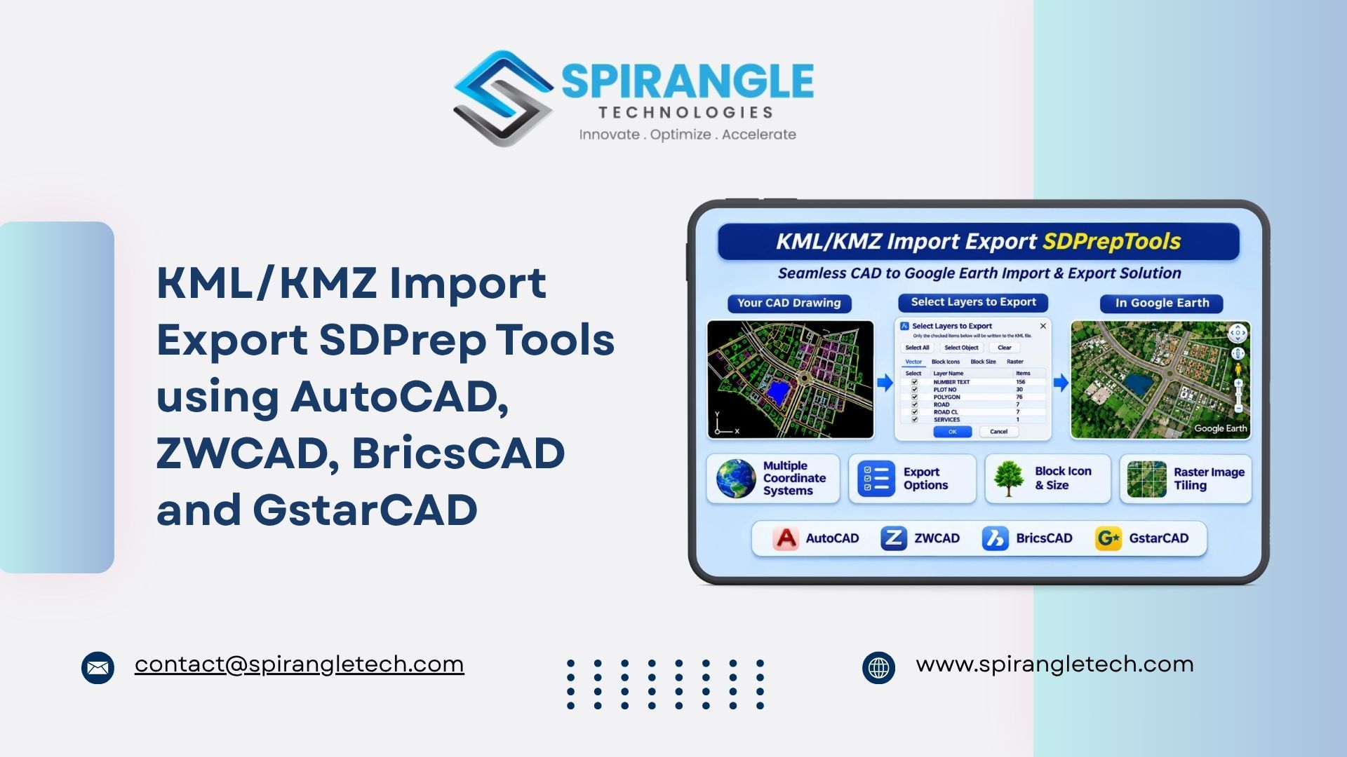
Transform Your CAD Drawings into Google Earth with KML/KMZ SDPrep Tools
Working with geospatial data often requires seamless communication between CAD applications and Google Earth. Converting CAD drawings into geospatial formats while maintaining their coordinates, layers, blocks, and raster information can be a challenging task.
To simplify this workflow, we have developed KML/KMZ SDPrep Tools, a powerful CAD-based import and export solution that enables users to seamlessly transfer CAD drawing data into Google Earth-compatible KML/KMZ formats and import existing KML/KMZ files directly into CAD drawings.
With support for multiple coordinate reference systems, intelligent layer selection, block icon management, raster image processing, and customizable export settings, KML/KMZ SDPrep Tools provides an efficient workflow for managing geospatial information between CAD and Google Earth.
Whether you are working with infrastructure layouts, road networks, land parcels, utility networks, survey data, or large-scale mapping projects, this tool helps simplify your geospatial data workflow
1. KML/KMZ Import – Bring Google Earth Data into CAD
The ImportKML functionality allows users to import KML and KMZ files directly into their CAD environment.
The tool imports the following entities into the CAD drawing: Lines, Polylines, Polygons, Points, Blocks, Hatches, Text, and MText.
First, the user clicks the ImportKML button and then chooses the KML or KMZ file to import (only KML and KMZ files can be imported). After the file is chosen, the Coordinate Datum Setup window appears. This interface allows users to select the appropriate coordinate system before starting the import process
Multiple Coordinate System Support
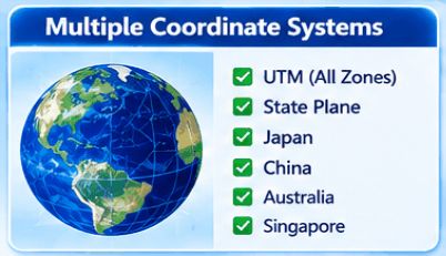
One of the key features of KML/KMZ SDPrep Tools is its support for different coordinate reference systems, allowing users to work with geospatial data from different regions.
The supported coordinate systems include:
- UTM (Universal Transverse Mercator): Supports different UTM zones and Northern and Southern hemispheres.
- State Plane Coordinate Systems: Supports regional State Plane coordinate systems for accurate mapping.
- Japan Coordinate Systems: Supports national and regional grid systems used in Japan.
- China Coordinate Systems: Supports regional coordinate systems used for mapping applications in China.
- Australia Coordinate Systems: Supports coordinate reference systems used across Australia.
- Singapore Coordinate Systems: Supports Singapore's national and regional coordinate systems.
Users can select the required coordinate system and configure the necessary parameters before proceeding with the import operation.
Once the coordinate system is selected, clicking the OK button starts the import process, allowing the KML/KMZ data to be brought into the CAD drawing.
This functionality helps users work with geospatial information from different regions while maintaining the appropriate coordinate reference
2. KML/KMZ Export – Convert CAD Drawings into Google Earth
The ExportKML functionality enables users to export CAD drawing information into Google Earth-compatible KML/KMZ files.
The tool reads the following CAD entities: Lines, Polylines, Polygons, Points, Blocks, Hatches, Raster Image Text, and MText.
After clicking the KML_Export button, the Coordinate Datum Setup window appears, where users can configure the coordinate system and offset parameters.
Coordinate System Selection and Offset Configuration
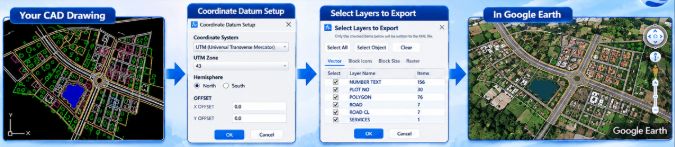
Users can select the required coordinate system according to their project requirements.
The export interface also provides two optional offset parameters:
- X Offset: Allows users to shift the exported drawing along the X-axis.
- Y Offset: Allows users to shift the exported drawing along the Y-axis.
Both offset values are optional, and users can leave them at their default values of 0.0 when no adjustment is required.
These offsets are applied to the exported KML/KMZ output without modifying the original CAD drawing.
Once the coordinate system and offset values are configured, users can click the OK button to proceed to the Export Layer Selection interface.
3. Advanced Export Layer Selection Interface
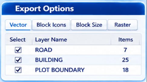
The Export Layer Selection interface provides users with complete control over which CAD elements should be included in the exported KML/KMZ file.
Instead of exporting the entire drawing, users can select specific layers, objects, blocks, and raster images according to their requirements.
The interface includes four main tabs:
- Vector
- Block Icons
- Block Size
- Raster
It also provides three useful selection options: Select All, Select Object, and Clear.
Select All
The Select All button allows users to select all available items in the current selection list. This is particularly useful when users want to export all the available CAD elements without manually checking each item.
Select Object
The Select Object functionality allows users to select specific objects directly from the CAD drawing.
Once the user clicks Select Object and selects the required objects, only those selected objects and their corresponding layers are displayed in the Vector tab for export.
This feature is especially useful when users want to export only a particular portion of a large CAD drawing.
Clear
The Clear button allows users to clear the currently selected checkboxes, making it easy to reset their selection and choose different elements.
These selection options provide flexibility and help users maintain better control over the export process.
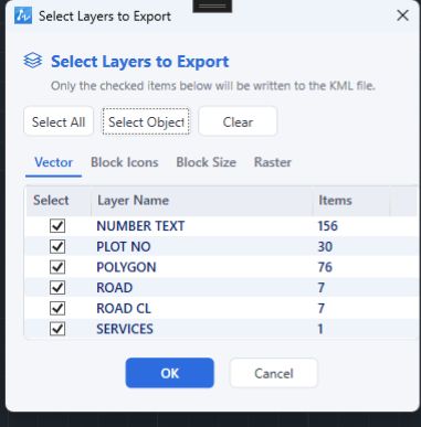
4. Vector Tab – Export CAD Drawing Entities by Layer
The Vector tab displays the available CAD drawing entities organized according to their respective layers.
Supported entities include Lines, Polylines, Polygons, Points, Blocks, Hatches, Text, and MText.
It provides information such as:
- Layer Name
- Number of Items
- Selection Checkbox
Users can select or deselect individual layers depending on which drawing elements they want to export.
For example, a drawing may contain layers such as:
- NUMBER TEXT
- PLOT NO
- POLYGON
- ROAD
- ROAD CL
- SERVICES
Each layer displays the number of associated objects, allowing users to understand the contents of their drawing before exporting.
Only the checked items will be included in the generated KML/KMZ file.
This layer-based export functionality makes it easier to manage large CAD drawings and export only the required geospatial information.
5. Block Icons Tab – Intelligent Block and Icon Management
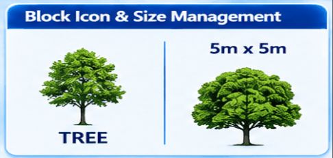
Blocks are commonly used in CAD drawings to represent trees, buildings, utilities, infrastructure elements, and other objects.
KML/KMZ SDPrep Tools provides a dedicated Block Icons tab to manage the relationship between CAD blocks and their corresponding Google Earth icons.
The interface displays the available block names along with their associated icon names
Automatic Block and Icon Matching
The tool allows users to match block names with corresponding icon names.
For example:
- CAD Block Name: TREE
- Icon Name: TREE
When a matching icon is available, it can be associated with the corresponding CAD block during export.
Zoom to Selected Block
Users can select a particular block from the list to locate and zoom in on its position within the CAD drawing.
This makes it easier to identify blocks, verify their placement, and manage their associated icons.
Add New Icon
Users are not limited to the available default icons.
If a user wants to assign a different icon to a block, they can use the Icon selection field, navigate to the bottom of the list, and select Add New Icon.
This allows users to add custom icons and associate them with the required CAD blocks.
As a result, users can customize the visual representation of blocks when viewing exported data in Google Earth.
6. Block Size Tab – Block Size-Based Export
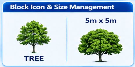
Different blocks in a CAD drawing can represent objects of different physical sizes.
For example, a tree symbol may represent a small object, whereas a building block may represent a much larger structure.
To handle these differences, KML/KMZ SDPrep Tools provides a dedicated Block Size tab.
This tab displays the available blocks along with their corresponding dimensions
Automatic Size-Based Representation
The tool provides a default block size threshold of 5 × 5 metres.
Based on this threshold:
- Blocks smaller than the configured size are represented using their associated icons.
- Blocks larger than the configured size are exported using their actual block geometry.
Users can also modify the default block size threshold according to their project requirements.
This functionality helps provide an appropriate visual representation of different objects in Google Earth while maintaining flexibility for different types of CAD projects.
7. Raster Tab – Advanced Raster Image and Tile Management
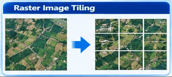
Raster images are an important part of many geospatial projects, especially when working with aerial imagery, orthophotos, satellite images, and large geographical maps.
KML/KMZ SDPrep Tools includes a dedicated Raster tab to manage raster images during the export process.
The Raster tab displays the following information:
- Image Name: Displays the name of the raster image.
- Image Path: Displays the location of the original image file.
- Pixel Size: Displays the pixel dimensions of the image.
- Tile Size: Allows users to configure the image tile size.
Intelligent Raster Image Tiling
Large raster images can be difficult to manage as a single image in Google Earth.
To address this, the tool provides an automatic image tiling mechanism.
The default tile size is 8192 pixels.
The functionality works as follows:
- If the image width or height exceeds the configured tile size, the image is divided into smaller tiles.
- If the image dimensions are within the configured tile size, the image is processed without dividing it into multiple tiles.
- Users can configure the tile size according to their requirements.
- The minimum supported tile size is 512 pixels.
This approach helps manage large raster images more efficiently and makes them suitable for integration into Google Earth
8. KML Settings – Customize Entity Width and Opacity
KML/KMZ SDPrep Tools also provides a dedicated KMLSetting option to customize the visual appearance of exported CAD entities.
Users can manage:
- Width: Controls the displayed width of supported vector entities.
- Opacity: Controls the transparency of supported CAD entities.
These settings help users customize the appearance of exported drawing elements and improve the readability of geospatial data in Google Earth.
By adjusting width and opacity, users can create clearer visual representations of roads, boundaries, and other supported CAD entities such as Lines, Polylines, Polygons, Points, Blocks, Hatches, Text, and MText.
9. Complete Import and Export Workflows
KML/KMZ SDPrep Tools provides an integrated workflow for importing and exporting geospatial data between CAD applications and Google Earth. Both workflows are described below.
The import workflow brings Lines, Polylines, Polygons, Points, Blocks, Hatches, Text, and MText from the KML/KMZ file into the CAD drawing.
Import Workflow: KML/KMZ to CAD

The complete import workflow can be summarized as follows:
- Click the KmlImport button.
- Select the required coordinate system.
- Select the KML or KMZ file to import.
- Click OK to proceed.
- Click the KML_Export button.
- Click OK to confirm.
- Open the result in Google Earth to view the data.
Export Workflow: CAD to Google Earth

The complete export workflow can be summarized as follows:
- Open the CAD drawing containing the required entities (Lines, Polylines, Polygons, Points, Blocks, Hatches, Text, and MText) and raster images.
- Click the ExportKML button.
- Select the required coordinate system.
- Configure the optional X Offset and Y Offset values if necessary.
- Click OK to proceed.
- Select the required CAD layers using the Vector tab.
- Use Select All, Select Object, or Clear according to the export requirements.
- Configure the block and icon associations in the Block Icons tab.
- Set the required block size threshold in the Block Size tab.
- Configure raster image and tile settings in the Raster tab.
- Click OK to start the export process.
- The tool generates the KML/KMZ output along with the required image tiles and resource folders.
- Open the exported KML/KMZ file in Google Earth to view the CAD drawing data.
10. Supported CAD Software and Versions
KML/KMZ SDPrep Tools supports a wide range of popular CAD platforms, so users can work with their preferred CAD software to import and export KML/KMZ files.

This multi-platform support allows teams using different CAD applications to follow the same CAD to Google Earth workflow.
11. Key Features and Benefits of KML/KMZ SDPrep Tools
KML/KMZ SDPrep Tools is designed to make CAD and geospatial data exchange easier, more flexible, and more efficient.
Key Features:
- Seamless KML and KMZ import into CAD drawings.
- Support for GstarCAD, AutoCAD, BricsCAD and ZWCAD across multiple versions.
- CAD drawing export to Google Earth-compatible KML/KMZ formats.
- Support for UTM coordinate systems and different UTM zones.
- Support for State Plane Coordinate Systems.
- Support for national and regional coordinate systems, including Japan, China, Australia, and Singapore.
- Optional X and Y offset configuration during export.
- Layer-based CAD entity selection and export.
- Import and export support for Lines, Polylines, Polygons, Points, Blocks, Hatches, Text, and MText.
- Select All, Select Object, and Clear functionality.
- Dedicated block icon management.
- Automatic block and icon matching.
- Custom icon support.
- Zoom-to-block functionality within CAD.
- Configurable block size threshold.
- Raster image information and management.
- Automatic raster image tiling for large images.
- Configurable tile size with a default of 8192 pixels.
- Automatic export folder and resource organization.
- Customizable KML entity width and opacity.
Conclusion
KML/KMZ SDPrep Tools brings CAD and Google Earth workflows together through a comprehensive import and export solution.
With its multiple coordinate system support, intelligent layer selection, block icon management, size-based block representation, raster image tiling, and customizable KML settings, the tool provides users with greater flexibility and control over their geospatial data.
Whether you are preparing infrastructure layouts, road networks, utility drawings, land parcel maps, or large raster-based mapping projects, KML/KMZ SDPrep Tools helps simplify the process of converting CAD information into Google Earth-compatible data.
Simplify your CAD-to-Google Earth workflow with KML/KMZ SDPrep Tools – making geospatial data exchange smarter, easier, and more efficient.
Contact Us:
Website: www.spirangletech.com
Contact: [email protected]